
2. Study of pressure head variation of flow over ogee weir
2.1. Objectives
- To study pressure head variation of flow at different sections of ogee weir.
- To study pressure head variation of flow at different sections of ogee weir by changing flows.
2.2. Apparatus
- Ogee weir
- Point gauge
- S6 tilting flume assembly
2.3. Related theory
2.3.1. Ogee spillway
Ogee spillway is widely used with concrete, masonry, arch and buttress dams. Such a spillway can be easily used on valleys where width of the river is sufficient to provide the required crest length and the river bed below can be protected from scour at moderate costs. The profile of this spillway is made in accordance with the shape of the lower nappe of a freely falling jet, over a duly ventilated sharp crested weir as shown in figure 2.1.
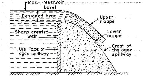
Figure 2.1: section of an ogee spillway with vertical U/S face
The shape of the lower nappe of freely falling jet over a sharp crested weir can be determined by the principle of projectile. It generally rises slightly (to point C) as it originates from the crest (O) of a sharp crested weir and then falls to make a parabolic form. Now, if the space between the sharp crested weir and lower nappe is filled with concrete or masonry, the weir so formed will have a profile similar to an ‘ogee’ (S shaped curve in section) and hence called an ogee weir or an ogee spillway. This lower nappe will then become the crest of the spillway. Since the lower nappe of the freely falling jet will be different for different heads over the crest of the sharp crested weir, the profile of the ogee weir is generally confined to the lower nappe that would be obtained for maximum head over the spillway.
2.3.2. Cavitation
The crest of the ogee spillway can be made to conform only to one particular nappe that would be obtained at one particular head. This head is called the designed head and represented by Hd but in practice, the actual head of water on the spillway crest, called the operating head, may be less or more than the designed head. If this operating head on the spillway is more than the designed head, the lower nappe of the falling jet may leave the ogee profile thereby generating negative pressure at the point of separation. The generation of vacuum or negative pressure may lead to formation of bubbles or cavities in the water. These cavities or bubbles filled with air, vapour and other gases are formed in a liquid, whenever the absolute pressure (atmospheric pressure-vacuum pressure) of the liquid is close to its vapour pressure, so as to commence evaporation. Such a condition may arise when the head of water is more than the designed head and the consequent high velocity jet causes reduced pressures or negative pressures in the lower region of the water jet.
Such cavities on moving downstream may enter a region where the absolute pressure is much higher (i.e. more vacuum). This causes the vapour in the cavity to condense and return to liquid with an implosion or collapse of the cavity. When the cavity collapses, extremely high pressures are generated. The continuous bombardment of these implosions will thus take place near the surface of the spillway, causing fatigue failure of its material. The small particles of concrete or masonry are this broken away, causing formation of pits on its surface and giving the surface a spongy appearance. This damaging action of cavitation is called pitting. The cavitation plus the vibrations from the alternate making and breaking of contact between the water and face of the spillway, may thus result in serious structural damages to the spillway is more than the designed head, cavitation may occur. On the other hand, if the head of water over the spillway is less than the designed head, the falling jet would adhere to the crest of the ogee spillway, creating positive hydrostatic pressures and thereby reducing the discharge coefficient of the weir.
2.4. Procedure
- Set the slope of S6 tilting flume to zero.
- Attach the ogee spillway to the tilting flume
- Attach the pipes from ogee spillway to the piezometers.
- Turn the pump on and note the differential manometer readings to compute the discharge.
- Note the piezometric values for particular discharge for all the tapings.
- Repeat the above procedure for various discharges
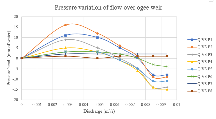
- Plot graph between various discharges and pressure heads at different tappings.
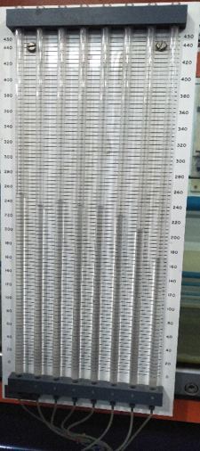 (a)
(a)
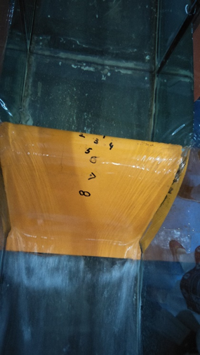
(b)
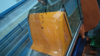
(c)
Figure 2.2: (a) Piezometers (b), (c) Ogee spillway with marked taping numbers
2.5. Observations and calculations
2.5.1. Relation between pressure head and various discharges
| Least count of piezometer = 5 mm of water | ||||||||||
| Sr. no. | Δ H | Q | P1 | P2 | P3 | P4 | P5 | P6 | P7 | P8 |
| mm | m3/s | mm | mm | mm | mm | mm | mm | mm | mm | |
| 1 | 0 | 0 | 240 | 220 | 235 | 233 | 234 | 224 | 208 | 172 |
| 2 | 5 | 0.002828 | 251 | 236 | 244 | 238 | 237 | 227 | 210 | 173 |
| 3 | 15 | 0.004898 | 250 | 232 | 240 | 236 | 237 | 227 | 210 | 172 |
| 4 | 25 | 0.006323 | 245 | 226 | 235 | 232 | 233 | 226 | 210 | 173 |
| 5 | 35 | 0.007481 | 240 | 221 | 230 | 227 | 229 | 224 | 210 | 173 |
| 6 | 45 | 0.008483 | 232 | 211 | 221 | 219 | 223 | 221 | 210 | 173 |
| 7 | 55 | 0.009378 | 232 | 211 | 221 | 218 | 223 | 220 | 210 | 173 |
| Sr. no. | Q | P1 | P2 | P3 | P4 | P5 | P6 | P7 | P8 |
| m3/s | mm | mm | mm | mm | mm | mm | mm | mm | |
| 1 | 0 | 0 | 0 | 0 | 0 | 0 | 0 | 0 | 0 |
| 2 | 0.002828 | 11 | 16 | 9 | 5 | 3 | 3 | 2 | 1 |
| 3 | 0.004898 | 10 | 12 | 5 | 3 | 3 | 3 | 2 | 0 |
| 4 | 0.006323 | 5 | 6 | 0 | -1 | -1 | 2 | 2 | 1 |
| 5 | 0.007481 | 0 | 1 | -5 | -6 | -5 | 0 | 2 | 1 |
| 6 | 0.008483 | -8 | -9 | -14 | -14 | -11 | -3 | 2 | 1 |
| 7 | 0.009378 | -8 | -9 | -14 | -15 | -11 | -4 | 2 | 1 |
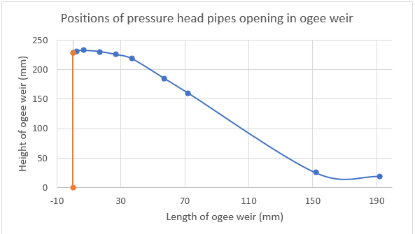
2.5.2. Position of pressure head pipes in ogee spillway
| Pipe # | Horizontal axis | Height | Width |
| mm | mm | mm | |
| 1 | 5238 | 228 | 0 |
| 2 | 5240 | 231 | 2 |
| 3 | 5245 | 232 | 7 |
| 4 | 5255 | 230 | 17 |
| 5 | 5265 | 225 | 27 |
| 6 | 5275 | 218 | 37 |
| 7 | 5295 | 185 | 57 |
| 8 | 5310 | 160 | 72 |
| 5390 | 25 | 152 | |
| 5430 | 19 | 192 |
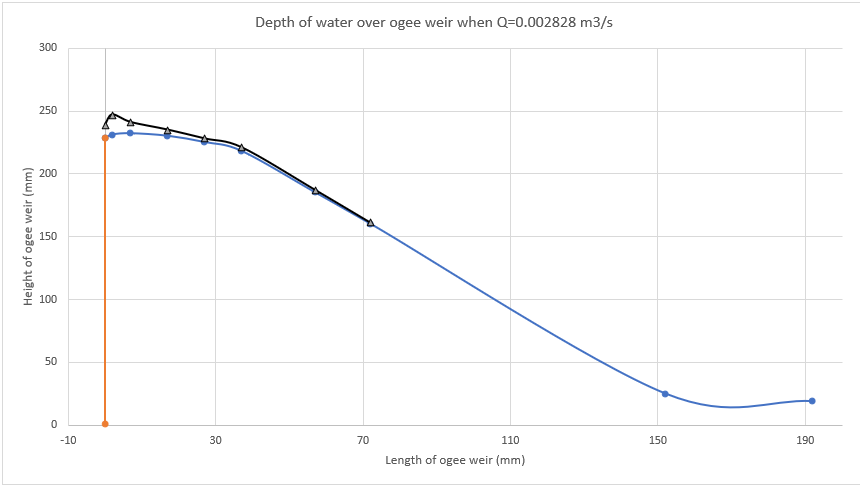
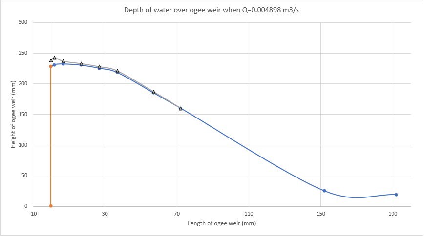
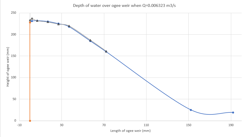
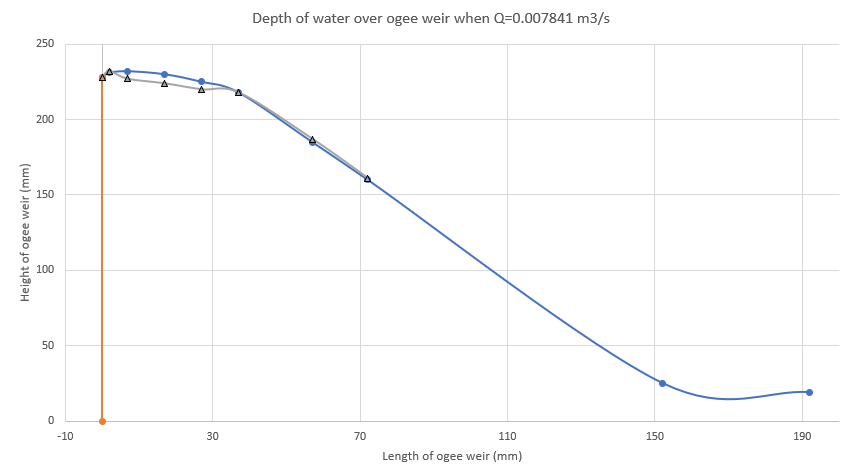
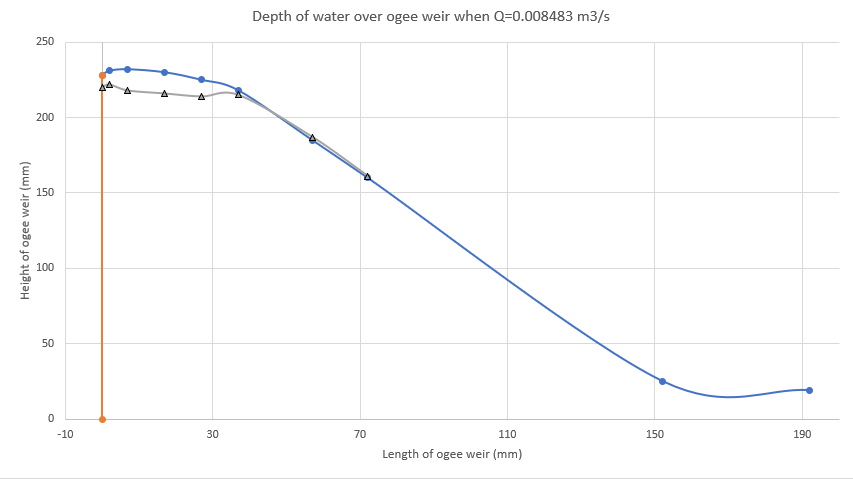
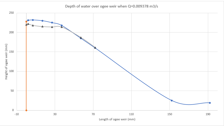
2.5.3. Variation of static head over ogee spillway with varying discharge
|
Marking # |
Elevation head |
Q=0.002828 m3/s | Q=0.004898 m3/s | Q=0.006323 m3/s | Q=0.007481 m3/s | Q=0.008483 m3/s | Q=0.009378 m3/s | ||||||
| Pressure head | Static head | Pressure head | Static head | Pressure head | Static head | Pressure head | Static head | Pressure head | Static head | Pressure head | Static head | ||
| Mm | mm | mm | mm | mm | mm | mm | mm | mm | mm | mm | mm | mm | |
| 1 | 228 | 11 | 239 | 10 | 238 | 5 | 233 | 0 | 228 | -8 | 220 | -8 | 220 |
| 2 | 231 | 16 | 247 | 12 | 243 | 6 | 237 | 1 | 232 | -9 | 222 | -9 | 222 |
| 3 | 232 | 9 | 241 | 5 | 237 | 0 | 232 | -5 | 227 | -14 | 218 | -14 | 218 |
| 4 | 230 | 5 | 235 | 3 | 233 | -1 | 229 | -6 | 224 | -14 | 216 | -15 | 215 |
| 5 | 225 | 3 | 228 | 3 | 228 | -1 | 224 | -5 | 220 | -11 | 214 | -11 | 214 |
| 6 | 218 | 3 | 221 | 3 | 221 | 2 | 220 | 0 | 218 | -3 | 215 | -4 | 214 |
| 7 | 185 | 2 | 187 | 2 | 187 | 2 | 187 | 2 | 187 | 2 | 187 | 2 | 187 |
| 8 | 160 | 1 | 161 | 0 | 160 | 1 | 161 | 1 | 161 | 1 | 161 | 1 | 161 |
2.6. Comments
- At taping number 2, there is more pressure head than that of other tapings.
- The maximum height of ogee spillway is at taping number 3 and it is 232 mm.
- With increase in discharge, pressure head is decreasing. The reason is that when there is increase in discharge, the velocity increases. Thus, to satisfy Bernoulli’s theorem, when velocity increases, kinetic energy increases and pressure must be reduced to keep the sun of equation constant. According to Bernoulli’s equation sum of pressure energy, kinetic energy and potential energy must be constant at 2 sections.
- When velocity of particles of media is quite high, they would be replaced to some other location creating a vacuum at former place, that’s why there is reduction in pressure head when discharge is increased.