
PENETRATION TEST ON BITUMINOUS MATERIALS
Code: ASTM: D 5/D 5 M-13
SCOPE &SIGNIFICANCE:
This test method covers determination of the penetration of semi-solid and solid bituminous materials.
- The penetration test is used as a measure of consistency. Higher values of penetration indicates softer consistency.
- The test is widely used world over for classifying bituminous materials into different grades.
- Depending upon the climatic conditions and type of construction bitumen of different penetration grades are used. Commonly used grades are 30/40, 60/70 and 80/100.
- In warmer regions, lower penetration grades are preferred and in colder regions bitumen with higher penetration values are used.
- The test is not intended to estimate consistency of softer materials like cut back which are usually graded by viscosity test.
RELATED THEORY:
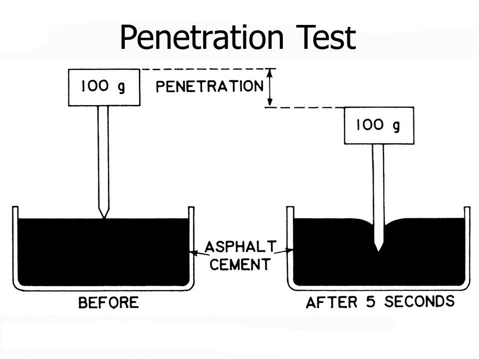
PENETRATION
Consistency of a bituminous material expressed as the distance in tenths of a millimeter that a standard needle vertically penetrates a sample of the material under known conditions of loading, time, and temperature.
SOURCES OF BITUMEN:
Bitumen is generally obtained from the following three sources;
- i)- Naturally occurring (in West Indies).
- ii)- Extracted from Limestone and Sandstone (procedure adopted in USA).
- iii)- From Oil Refineries (this is the major source of bitumen in Pakistan).
GRADES OF BITUMEN:
Bitumen is usually characterized in the following three types of grades;
- i)- Viscosity grades
- ii)- Penetration grades
- iii)- Density grades
FACTS ABOUT BITUMEN:
- Bitumen is both flammable and combustible.
- Bitumen becomes volatile at high temperatures.
- The working temperature of the bitumen must be at least 100°C less than the flash point.
- By repeated heating and cooling of bitumen, more and more volatiles will be ejected and the properties of bitumen will be altered.
PENETRATION GRADES OF BITUMEN

Source “Highways Colm A O’ Flaherty”
BITUMEN GRADE FOR ROAD PAVING:
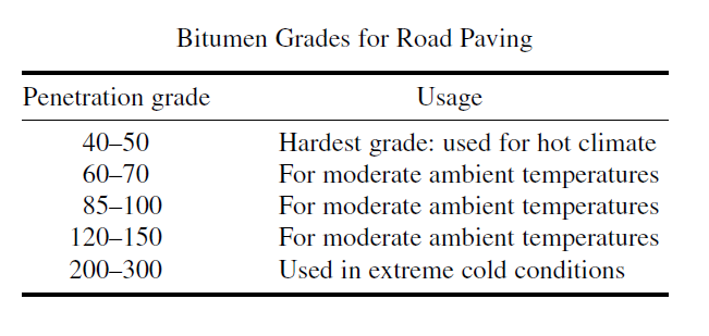
Source: “Petroleum fuels manufacturing handbook by Surendar Prakash PHD”
ASPHALT CEMENT GRADE ACCORDING TO PENETRATION VALUE
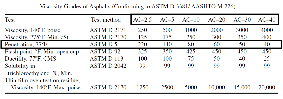
Source: “Petroleum fuels manufacturing handbook by Surendar Prakash PHD”
APPARATUS:
- Penetration Apparatus
Any apparatus that permits the needle holder (spindle) to move vertically without measurable friction and is capable to indicating the depth of penetration to the nearest 0.1 mm, will be acceptable. The weight of the spindle shall be 47.5 ± 0.05 gram. The total weight of the needle and spindle assembly shall be 50.0 ±0.05 grams. Weights of 50 ± 0.05 grams and 100 ± 0.05 grams shall also be provided for total loads of 100 gram and 200 gram, as required for some conditions of the test. The surface on which the sample container rests shall be flat and the axis of the plunger shall be at approximately 90° to this surface. The apparatus shall have a leveling indicator. The spindle shall be easily detached for checking its weight.
- Penetration Needle:
The needle shall be made from fully hardened and tapered stainless steel; the standard needle shall be approximately 50 mm in length. The diameter of needle shall be 1.00 to 1.02 mm. It shall be symmetrically tapered at one end by grinding to a cone having an angle between 8.7 and 9.7° over the entire cone length. The cone should be coaxial with the straight body of the needle. The truncated tip of the cone shall be within the diameter limits of 0.14 and 0.16 mm and square to the needle axis within 2°. The entire edge of the truncated surface at the tip shall be sharp and free of burrs. The needle shall he mounted in a non-corroding metal ferrule. The exposed length of the standard needle shall be within the limits of 40 and 45 mm and the exposed length of the long needle shall be 50 to 55 mm. The needle shall be rigidly mounted in the ferrule. The weight of the ferrule needle assembly should be2.50±0.05 grams.

Fig. Penetration needle
- Sample Container:
A metal or glass cylindrical, flat-bottom container of the following dimensions shall be used:
| PENETRATION | DIAMETER
(mm) |
INTERNAL DEPTH
(mm) |
| Below 40 | 33-50 | 8-16 |
| Below 200 | 55 | 35 |
| Between 200 & 350 | 55-75 | 45-70 |
| Between 350 & 500 | 55 | 70 |
- Water Bath:
A bath having a capacity of at least 10 Liter and capable of maintaining a temperature of 25 ± 0.1 °C or other temperature of test within 0.1 °C. The bath shall have a perforated shelf supported in a position not less than 50 mm from the bottom and not less than 100 mm below the liquid level in the bath. If penetration tests are not to be made in the bath itself, an additional shelf strong enough to support the penetrometer shall be provided. Brine may be used in the bath for determinations at low temperatures.
- Transfer Dish
When used, the transfer dish shall have a capacity of at least 350 mL and of sufficient depth of water to cover the large sample container. It shall be provided with some means for obtaining a firm bearing and preventing rocking of the container. A three-legged stand with three-point contact for the sample container is a convenient way of ensuring this.
- Timing Device:
For hand-operated-penetrometers any convenient timing device such as an electric timer, a stop watch, or other spring activated device may be used provided it is graduated in 0.1 s or less and is accurate to within ±0.1 s for a 60-s interval. An audible seconds counter adjusted to provide 1 beat each 0.5 s may also be used. The time for a 11-count interval shall be 5 ± 0.1 s. Any automatic timing device attached to a penetrometer shall be accurately calibrated to provide the desired test interval within ±0.1 s.
- Thermometers:
Calibrated liquid-in-glass thermometers of suitable range with subdivisions and maximum scale error of 0.1 °C or any other thermometric device of equal accuracy, precision and sensitivity shall be used.
PREPARATIONOF TEST SPECIMEN:
- If the sample is not sufficiently fluid as received, heat the sample with care, stirring when possible to prevent local overheating, until it has become sufficiently fluid to pour. In no case should the temperature be raised to more than 60°C above the expected softening point for tar pitch, or to more than 90°C above it for petroleum asphalt (bitumen). Heat samples for the minimum time necessary to ensure that they are sufficiently fluid. Stir to ensure that the sample is homogeneous. Avoid incorporating bubbles into the sample.
- Pour the sample into the sample container to a depth such that, when cooled to the temperature of test, the depth of the sample is at least 120% of the depth to which the needle is expected to penetrate. Pour separate portions for each variation in test conditions. If the sample container is less than 65 mm in diameter and the expected penetration is greater than 200, pour three separate portions for each variation in test conditions.
- Allow to cool in air at a temperature between 15 and 30°C for 45 min to 1.5 h for the small (33 × 16 mm or less) container, 1 to 1.5 h for the medium (55 × 35 mm) container and 1.5 to 2 h for larger containers. Then place the samples together with the transfer dish, if used, in the water bath maintained at the prescribed temperature of test. Allow the small (33 × 16 mm or less) container to remain for 45 min to 1.5 h, the medium (55 × 35 mm) container to remain for 1 to 1.5 h and the larger containers to remain for 1.5 to 2 h.
TEST CONDITIONS
Where the conditions of test are not specifically mentioned, the temperature, load, and time are understood to be 25 °C, 100 gram and 5 seconds, respectively. Other conditions may be used for special testing, such as the following:
| TEMPERATURE
(oC) |
LOAD
(gm.) |
TIME
(sec) |
| 0 | 200 | 60 |
| 4 | 200 | 60 |
| 45 | 50 | 5 |
| 46.1 | 50 | 5 |
In such cases the specific conditions of test shall be reported.
PROCEDURE:
- Examine the needle holder and guide to establish the absence of water and other extraneous materials. If the penetration is expected to exceed 350 use a long needle, otherwise use a short needle. Clean a penetration needle with toluene or other suitable solvent, dry with a clean cloth, and insert the needle into the penetrometer. Unless otherwise specified place the 50-g weight above the needle, making the total weight 100 ± 1 g.
- If tests are to be made with the penetrometer in the bath, place the sample container directly on the submerged stand of the penetrometer. Keep the sample container completely covered with water in the bath. If the tests are to be made with the penetrometer outside the bath, place the sample container in the transfer dish, cover the container completely with water from the constant temperature bath and place the transfer dish on the stand of the penetrometer.
- Using the level indicator, ensure that the apparatus is level.
- Either note the reading of the penetrometer dial or bring the pointer to zero. Position the needle by slowly lowering it until its tip just makes contact with the surface of the sample. This is accomplished by bringing the actual needle tip into contact with its image reflected on the surface of the sample from a properly placed source of light. Quickly release the needle holder for the specified period of time and adjust the instrument to measure the distance penetrated in tenths of a millimetre. If the container moves, ignore the result
- Make at least three determinations at points on the surface of the sample not less than 10 mm from the side of the container and not less than 10 mm apart. If the transfer dish is used, return the sample and transfer dish to the constant temperature bath between determinations. Use a clean needle for each determination. If the penetration is greater than 200, use at least three needles leaving them in the sample until the three determinations have been completed. If the sample container is less than 65 mm in diameter and the expected penetration is greater than 200, make one penetration in each of the three separate containers prepared.
REPORT
Report to nearest whole unit the average of three penetrations whose values do not differ by more than the following:
| PENETRATION | 0 to 49 | 50 to 149 | 150 to 249 | 250 to 500 |
| Maximum difference between highest and lowest penetration | 2 | 4 | 12 | 20 |
PRECAUTIONS:
- The two penetrations should be at least 1cm away from each other or from the wall of the cup.
- One should not take more than 25sec to put the specimen in water after completing the test.
- Do not heat the specimen directly as this may result in localized heating causing bitumen to ignite.
OBSERVATIONS & CALCULATIONS
| GROUP # | PENETRATION | |
| READINGS | MEAN | |
| 1 | 47 | 46 |
| 44 | ||
| 46 | ||
| 2 | 54 | 50 |
| 49 | ||
| 48 | ||
| 3 | 63 | 61 |
| 61 | ||
| 60 | ||
RESULTS & COMMENTS:
- The temperature, load and time to be considered in the test was 25 0C, 100 g and 5 seconds respectively.
- For Group 1
Penetration range is from 0-49
Maximum difference between highest and lowest penetration is 2 (OK)
- For Group 2
Penetration range is from 50-149
Maximum difference between highest and lowest penetration is 4 (OK)
- For Group 3
Penetration range is from 50-149
Maximum difference between highest and lowest penetration is 4 (OK)
| Group no. | Mean penetration | Penetration grade | AC Grade | Usage |
| 1 | 46 | 40 Pen HD | AC 30 | Hot climate |
| 2 | 50 | 50 Pen | AC 30 | Hot climate |
| 3 | 61 | 50 Pen | AC 10 | Hot climate |
Hello everyone, it’s my first pay a quick visit at this web
site, and article is in fact fruitful for me, keep up posting these types of content.
my website … 먹튀검증
Thanks designed for sharing such a pleasant thinking, post is nice,
thats why i have read it fully