3. To measure energy dissipation downstream of spillway by various energy dissipation arrangements
3.1. Objectives:
- To observe formation of hydraulic jump in channel
- To note the sequent depths & to compare value of y2 by using formula
- To find the type of hydraulic jump formed in channel
- To find energy dissipation by using hydraulic jump
- To find energy dissipation by ski jump
- To find energy dissipation by chute blocks
- To find energy dissipation by gravel bed
- To compare the energy dissipation by various dissipators
3.2. Apparatus:
- S6 Tilting flume assembly
- Point gauge
- Ogee weir
- Downstream channel gate
- Ski jump
- Baffle/Chute blocks
- Gravel bed
3.3. Related theory:
3.3.1. Energy dissipation below overflow spillways
The water flowing over the spillway acquires a lot of kinetic energy by the time it reaches near tow of the spillway (because of conversion of potential energy into kinetic energy). If arrangements are not made to dissipate this huge kinetic energy of water, and if the velocity of water is not reduced, large scale scour can take place on the downstream side near the toe of the dam and away for it. Energy dissipators need to be designed for proper dissipation of high energy.
In general, the K.E. of this super critical flow can be dissipated in following ways:
- By converting the super critical flow into sub critical flow by hydraulic jump.
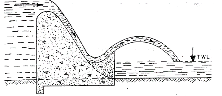
- By directing the flow of water into air and then making it fall away from the toe of the structure. The energy is dissipated by the aeration of jet and impact of water on the river bed. Though some scour will take place but it is too small or too far away from the dam to endanger it. Bucket type dissipators work on this principle.
- By providing auxiliary devices such as chute blocks, sills, baffle walls etc. in stilling basins.
3.3.2. Various cases of energy dissipators
3.3.2.1. Simple horizontal apron

Figure 3.1: Simple horizontal apron
3.3.2.2. Sloping apron above the bed
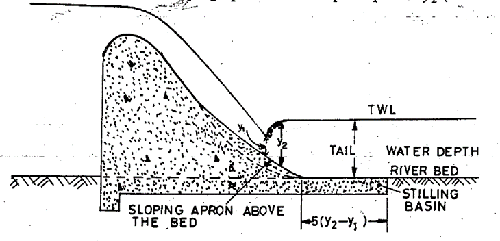
Figure 3.2: Sloping apron above the bed
3.3.2.3. Roller bucket
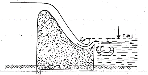
3.3.2.4. Ski jump bucket
3.3.2.5. Sloping apron below the bed
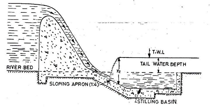
Figure 3.5: Sloping apron below the bed
3.3.2.6. Subsidiary dam construction
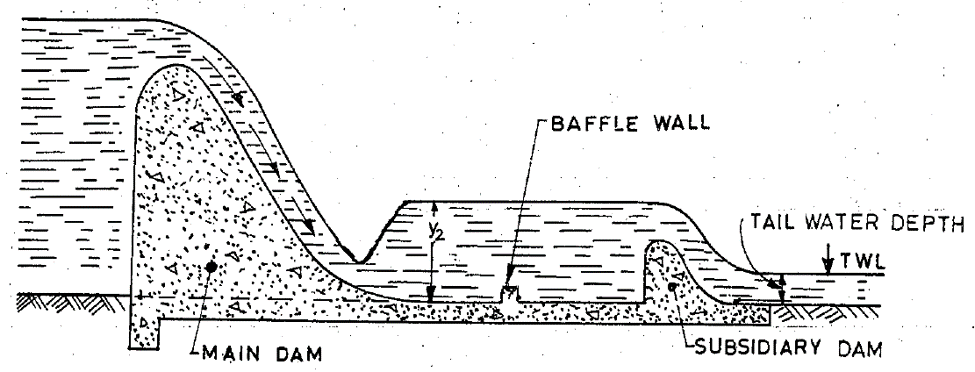
Figure 3.6: Subsidiary dam construction
3.3.2.7. Sloping apron partly above and partly below ground level
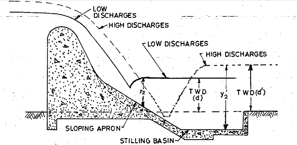
Figure 3.7: Sloping apron partly above and partly below ground level
3.3.3. Hydraulic jump
A hydraulic jump occurs when a supercritical stream meets a subcritical stream of sufficient depth. The supercritical stream jumps up to meet its alternate depth. While doing so it generates considerable disturbances in the form of large-scale eddies and a reverse flow roller with the result that the jump falls short of its alternate depth.
Figure 3.8. is a schematic sketch of a typical hydraulic jump in a horizontal channel. Section 1, where the incoming supercritical stream undergoes an abrupt rise in the depth forming the commencement of the jump, is called the toe of the jump. The jump proper consists of a steep change in the water-surface elevation with a reverse flow roller on the major part. The roller entrains considerable quantity of air and the surface has white, frothy and choppy appearance. The jump, while essentially steady, will normally oscillate about a mean position in the longitudinal direction and the surface will be uneven.
Section 2, which lies beyond the roller and with an essentially level water surface is called the end of the jump and the distance between Sections 1 and 2 is the length of the jump, Lj. The initial depth of the supercritical stream is y1 and y2 is the final depth, after the jump, of the subcritical stream. The two depths y1. And y2 at the ends of the jump are called sequent depths.
Due to high turbulence and shear action of the roller, there is considerable loss of energy in the jump between Sections 1 and 2. In view of the high energy loss, the nature of which is difficult to estimate, the energy equation cannot be applied to Sections 1 and 2 to relate the various flow parameters. In such situations, the use of the momentum equation with suitable assumptions is advocated. In fact, the hydraulic jump is a typical example where a judicious use of the momentum equation yields meaningful results.
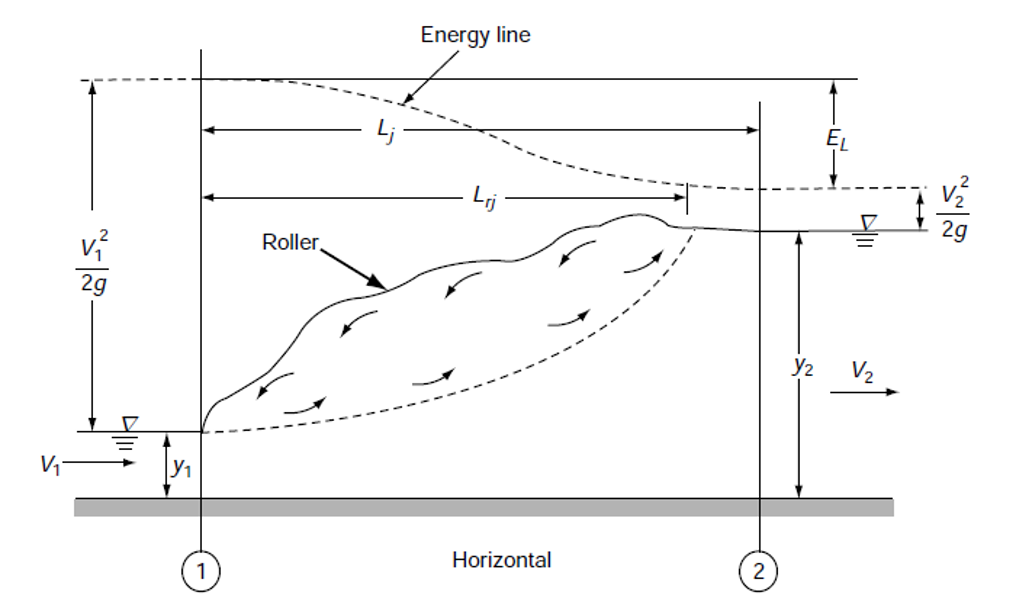
Figure 3.8. Sketch of hydraulic jump
3.3.3.1. Uses of hydraulic jump:
A hydraulic jump primarily serves as an energy dissipator to dissipate the excess energy of flowing water downstream of hydraulic structures, such as spillways and sluice gates. Some of the other uses are:
- Efficient operation of flow-measurement flumes
- Mixing of chemicals.
- To aid intense mixing and gas transfer in chemical processes
- In the desalination of sea water
- In the aeration of streams which are polluted by bio-degradable wastes
3.3.3.2. Hydraulic jump in a horizontal rectangular channel
3.3.3.3. Classification of hydraulic jumps
The hydraulic jumps in horizontal rectangular channels are classified into five categories based on the Froude number F1 of the supercritical flow, as follows:
- Undular Jump 1.0 < F1 ≤ 1.7
The water surface is undulating with a very small ripple on the surface. The sequent-depth ratio is very small and EL / E1 is practically zero. A typical undular jump is shown in Fig. 3.9.
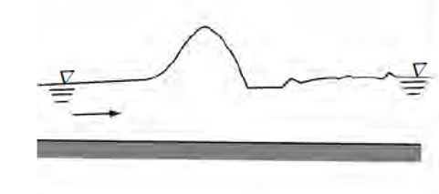
Figure 3.9: Undular hydraulic jump
- Weak Jump 1.7 < F1 ≤ 2.5
The surface roller makes its appearance at F1 ≈1.7 and gradually increases in intensity towards the end of this range, i.e. F1 ≈ 2.5. The energy dissipation is very small, is E L/ E1 about 5 per cent at F1 = 1.7 and 18 percent at F1 = 2.5. The water surface is smooth after the jump. Figure 3.10
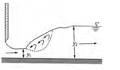
Figure 3.10: Weak hydraulic jump
- Oscillating Jump 2.5 < F1 ≤ 4.5
This category of jump is characterized by an instability of the high-velocity flow in the jump which oscillates in a random manner between the bed and the surface. These oscillations produce large surface waves that travel considerable distances downstream Fig. 3.11. Special care is needed to suppress the waves in stilling basins having this kind of jump. Energy dissipation is moderate in this range; EL / E1= 45 per cent at F1 = 4.5.
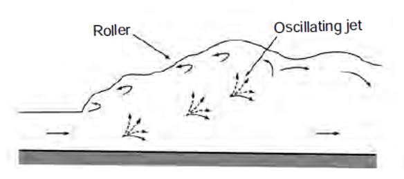
Figure 3.11: Oscillating hydraulic jump
- Steady Jump 4.5 < F1 ≤ 9.0
In this range of Froude numbers, the jump is well-established, the roller and jump action is fully developed to cause appreciable energy loss Fig. 3.12. The relative energy loss EL / E1 ranges from 45 per cent to 70 per cent in this, class of jump. The ‘steady jump’ is least sensitive in terms of the toe-position to small fluctuations in the tailwater elevation.

Figure 3.12: Steady hydraulic jump
- Strong or Choppy Jump F1 >9.0
In this class of jump the water surface is very rough and choppy. The water surface downstream of the jump is also rough and wavy Fig. 3.13. The sequent-depth ratio is large and the energy dissipation is very efficient with EL / E1values greater than 70 per cent.

Figure 3.13: Strong hydraulic jump
3.3.3.4. Hydraulic jump as energy dissipator
The high energy loss that occurs in a hydraulic jump has led to its adoption as a part of the energy-dissipator system below a hydraulic structure.
The downstream portion of the hydraulic structure where the energy dissipation is deliberately allowed to occur so that the outgoing stream can safely be conducted to the channel below is known as a stilling basin. It is a fully-paved channel section and may have additional appurtenances, such as baffle blocks and sills to aid in the efficient performance over a wide range of operating conditions. Stilling basins are so designed that not only a good jump with high energy-dissipation characteristics is formed within the basin but it is also stable. For economic considerations the basin must be as small as practicable.
3.3.3.5. Length of jump
The length of the jump Lj is an important parameter affecting the size of a stilling basin in which the jump is used. There have been many definitions of the length of the jump resulting in some confusion in comparing various studies. It is now usual to take the length of the jump as the horizontal distance between the toe of the jump to a section where the water surface levels off after reaching the maximum depth. Because the water-surface profile is very flat towards the end of the jump, large personal errors are introduced in the determination of the length Lj.
The approximate length of hydraulic jump can be calculated by following formula;
Lj=6.9 (y2 − y 1)
3.3.4. Energy dissipation by ski jump
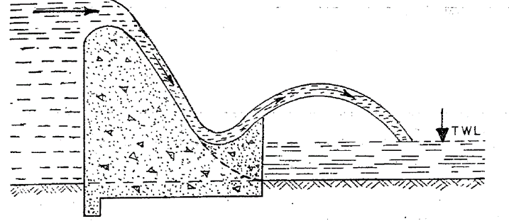
When tail water channel depth is insufficient or low at all discharges, ski jump bucket can be used as energy dissipator. If the tail water is very low, the water may shoot up out of the above bucket, and harmlessly into the river at some distance downstream of the bucket.
The ski jump bucket type of an energy dissipator requires sound and rocky river bed, because a part of the energy dissipation takes place by impact, although some of the energy is dissipated by diffusion and aeration.
3.3.5. Energy dissipation by chute blocks
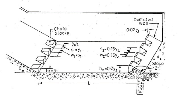
Chute blocks are a kind of serrated device (i.e. row of small projections like teeth of saw) and provided at the entrance of the stilling basin. The incoming jet of water is furrowed and partly lifted from the floor, producing a shorter length of jump than what would have been without them. They also help in stabilizing the flow and thus improve the jump performance.
3.3.6. Energy dissipation by gravel bed
If there is gravel bed downstream of spillway, it also acts as energy dissipator. The gravels are placed at stilling basin and when water strikes this type of bed, energy is dissipated.
3.4. Procedure:
- Set the slope of tilting flume at zero.
- Place the ogee spillway in the tilting flume and plaster the sides properly.
- Turn the pump ON so that water starts overflowing spillway.
- Note the readings of differential manometer and find discharge from calibrated table.
- Start closing the downstream gate to produce hydraulic jump.
- Note the sequent depths by depth gauge.
- Find the Froude’s number at upstream side and check the type of hydraulic jump formed.
- Find the initial energy loss.
- Repeat the steps for various discharges.
- Repeat the above procedure by placing ski jump bucket, baffle blocks and gravel bed downstream of spillway.
3.5. Observations and calculations
3.5.1. Energy dissipation by hydraulic jump
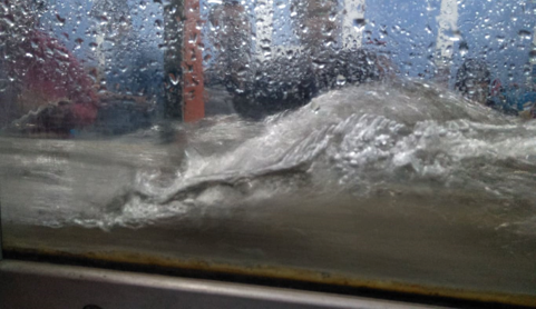
Figure 3.16: Hydraulic jump formation in flume
Width of flume = b = 300 mm Position of ogee spillway = 5250 mm
| Sr. no. | H1-H2 | Q | Sequent depths experimental | A1=by1 | V1=Q/A1 | Fn | Type of HJ | Length of jump, Lj | Y2 from eq. | E1 | A2=by2 | V2=Q/A2 | E2 | Energy loss EL | % of initial energy lost | |||
| X1 | Y1 | X2 | Y2 | |||||||||||||||
| mm | m3/s | mm | mm | mm | mm | m2 | m/s | mm | mm | m | m2 | m/s | m | m | % | |||
| 1 | 30 | 0.006928 | 5800 | 14 | 7400 | 78 | 0.0042 | 1.65 | 4.45 | Oscillating | 441.60 | 81 | 0.153 | 0.0234 | 0.30 | 0.082 | 0.070 | 46.0 |
| 2 | 40 | 0.007998 | 5800 | 15.6 | 7400 | 80 | 0.00468 | 1.71 | 4.37 | Oscillating | 444.36 | 89 | 0.164 | 0.024 | 0.33 | 0.086 | 0.079 | 47.9 |
| 3 | 50 | 0.008942 | 5800 | 17 | 7400 | 85 | 0.0051 | 1.75 | 4.29 | Oscillating | 469.20 | 95 | 0.174 | 0.0255 | 0.35 | 0.091 | 0.082 | 47.5 |
| 4 | 65 | 0.010195 | 5800 | 19 | 7400 | 88 | 0.0057 | 1.79 | 4.14 | Oscillating | 476.10 | 102 | 0.182 | 0.0264 | 0.39 | 0.096 | 0.086 | 47.5 |
| 5 | 70 | 0.01068 | 5800 | 23 | 7400 | 90 | 0.0069 | 1.55 | 3.26 | Oscillating | 462.30 | 95 | 0.145 | 0.027 | 0.40 | 0.098 | 0.047 | 32.5 |
Where

3.5.2. Energy dissipation by Ski jump bucket
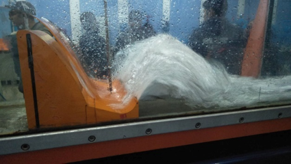
Figure 3.17: Ski jump formation in flume
Width of flume = b = 300 mm Position of ogee spillway = 5250 mm
| Sr. no. | H1-H2 | Q | Sequent depths experimental | A1=by1 | V1=Q/A | Fn | Type of HJ | E1 | A2=by2 | V2=Q/A2 | E2 | Energy loss EL | EL/E1 | % of initial energy lost | |||
| X1 | Y1 | X2 | Y2 | ||||||||||||||
| mm | m3/s | mm | mm | mm | mm | m2 | m/s | m | m2 | m/s | m | m | % | ||||
| 1 | 35 | 0.007481 | 5480 | 13 | 6700 | 53 | 0.0039 | 1.92 | 5.37 | Steady | 0.201 | 0.0159 | 0.47 | 0.064 | 0.136 | 0.679 | 67.9 |
| 2 | 45 | 0.008483 | 5480 | 16 | 6900 | 35 | 0.0048 | 1.77 | 4.46 | Oscillating | 0.175 | 0.0105 | 0.81 | 0.068 | 0.107 | 0.610 | 61.0 |
| 3 | 50 | 0.008942 | 5480 | 17 | 7000 | 34 | 0.0051 | 1.75 | 4.29 | Oscillating | 0.174 | 0.0102 | 0.88 | 0.073 | 0.101 | 0.579 | 57.9 |
| 4 | 60 | 0.009795 | 5480 | 18 | 7100 | 30 | 0.0054 | 1.81 | 4.32 | Oscillating | 0.186 | 0.009 | 1.09 | 0.090 | 0.095 | 0.513 | 51.3 |
| 5 | 65 | 0.010195 | 5480 | 19 | 7200 | 28 | 0.0057 | 1.79 | 4.14 | Oscillating | 0.182 | 0.0084 | 1.21 | 0.103 | 0.079 | 0.434 | 43.4 |
Where, Width of flume = b = 300 mm Position of ogee spillway = 5250 mm

3.5.3. Energy dissipation by chute blocks
Width of flume = b = 300 mm Position of ogee spillway = 5250 mm
| Sr. no. | No. of chute blocks layers | H1-H2 | Q | Sequent depths experimental | A1=by1 | V1=Q/A1 | Fn | Type of HJ | E1 | A2=by2 | V2=Q/A2 | E2 | Energy loss EL | % of initial energy lost | |||
| X1 | Y1 | X2 | Y2 | ||||||||||||||
| mm | m3/s | mm | mm | mm | mm | m2 | m/s | m | m2 | m/s | m | m | % | ||||
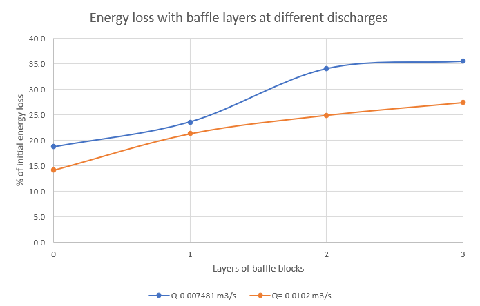
| 1 | 3 | 35 | 0.007481 | 5440 | 21 | 6500 | 38 | 0.0063 | 1.19 | 2.62 | Oscillating | 0.093 | 0.0114 | 0.66 | 0.060 | 0.033 | 35.4 |
| 2 | 2 | 35 | 0.007481 | 5440 | 19 | 6500 | 27 | 0.0057 | 1.31 | 3.04 | Oscillating | 0.107 | 0.0081 | 0.92 | 0.070 | 0.036 | 34.0 |
| 3 | 1 | 35 | 0.007481 | 5440 | 16 | 6500 | 19 | 0.0048 | 1.56 | 3.93 | Oscillating | 0.140 | 0.0057 | 1.31 | 0.107 | 0.033 | 23.6 |
| 4 | 0 | 35 | 0.007481 | 5440 | 15 | 6500 | 17 | 0.0045 | 1.66 | 4.33 | Oscillating | 0.156 | 0.0051 | 1.47 | 0.127 | 0.029 | 18.7 |
| 5 | 3 | 65 | 0.0102 | 5440 | 28 | 6500 | 43 | 0.0084 | 1.21 | 2.32 | Weak | 0.103 | 0.0129 | 0.79 | 0.075 | 0.028 | 27.4 |
| 6 | 2 | 65 | 0.0102 | 5440 | 26 | 6500 | 34 | 0.0078 | 1.31 | 2.59 | Oscillating | 0.113 | 0.0102 | 1.00 | 0.085 | 0.028 | 24.9 |
| 7 | 1 | 65 | 0.0102 | 5440 | 22 | 6500 | 26 | 0.0066 | 1.55 | 3.33 | Oscillating | 0.144 | 0.0078 | 1.31 | 0.113 | 0.031 | 21.3 |
| 8 | 0 | 65 | 0.0102 | 5440 | 20 | 6500 | 22 | 0.006 | 1.70 | 3.84 | Oscillating | 0.167 | 0.0066 | 1.55 | 0.144 | 0.024 | 14.1 |
Where

3.5.3.1. Energy loss with chute block layers at different discharges
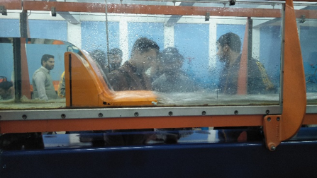
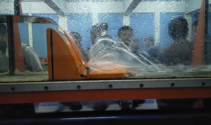
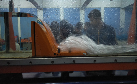
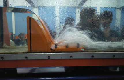
Figure 3.18: Ogee spillway with increasing number of chute block layers
3.5.4. Energy dissipation by gravel bed
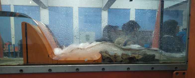
Figure 3.19: Energy dissipation by gravel bed
Width of flume = b = 300 mm Position of ogee spillway = 5250 mm
| Sr. no. | Q | Sequent depths experimental | A1=by1 | V1=Q/A1 | Fn | Type of HJ | E1 | A2=by2 | V2=Q/A2 | E2 | Energy loss EL | EL/E1 | % of initial energy lost | |||
| X1 | Y1 | X2 | Y2 | |||||||||||||
| m3/s | mm | mm | mm | mm | m2 | m/s | m | m2 | m/s | m | m | % | ||||
| 1 | 0.00748 | 5480 | 19 | 6700 | 51 | 0.0057 | 1.31 | 3.04 | Oscillating | 0.107 | 0.0153 | 0.49 | 0.063 | 0.044 | 0.408 | 40.8 |
| 2 | 0.00848 | 5480 | 20 | 6900 | 49 | 0.006 | 1.41 | 3.19 | Oscillating | 0.122 | 0.0147 | 0.58 | 0.066 | 0.056 | 0.458 | 45.8 |
| 3 | 0.00938 | 5480 | 23 | 7000 | 60 | 0.0069 | 1.36 | 2.86 | Oscillating | 0.117 | 0.018 | 0.52 | 0.074 | 0.043 | 0.370 | 37.0 |
| 4 | 0.0102 | 5480 | 25 | 7100 | 68 | 0.0075 | 1.36 | 2.75 | Oscillating | 0.119 | 0.0204 | 0.50 | 0.081 | 0.039 | 0.323 | 32.3 |
Where

3.6. Results
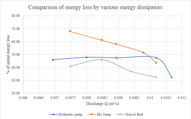
3.7. Comments
- With increase in discharge, % of initial energy lost is decreasing.
- With increase in discharge, Froude’s number will be decreased.
- With increase in discharge, the hydraulic jump is shifting towards weak jump.
- With increase in discharge, length of hydraulic jump will increase.
- The maximum amount of energy dissipated is by ski jump bucket then there is hydraulic jump and then gravel bed and then by chute blocks.


I adore this blog layout . How was it made? It is really good!
very good publish, i certainly love this website, keep on it