
1. Estimation of coefficient of weir for ogee weir
1.1. Objectives:
- To find coefficient of weir for ogee weir.
- To observe relationship between discharge and coefficient of weir.
- To observe relationship between discharge and head above crest of weir.
1.2. Apparatus:
- Ogee weir
- Point gauge
- S6 tilting flume assembly
1.3. Related theory:
1.3.1. Weir:
A weir or low head dam is a barrier across the horizontal width of a river that alters the flow characteristics of water and usually results in a change in the height of the river level. There are many designs of weir, but commonly water flows freely over the top of the weir crest before cascading down to a lower level.
1.3.2. Functions of weir:
Weirs are commonly used to prevent flooding, measure water discharge, and help render rivers more navigable by boat. In some locations, the terms dam and weir are synonymous, but normally there is a clear distinction made between the structures. A dam is usually specifically designed to impound water behind a wall, whilst a weir is designed to alter the river flow characteristics.
A common distinction between dams and weirs is that water flows over the top (crest) of a weir. Accordingly, the crest of an overflow spillway on a large dam may therefore be referred to as a weir. Weirs can vary in size both horizontally and vertically, with the smallest being only a few inches in height whilst the largest may be hundreds of metres long and many metres tall
1.3.3. Flow measurement
Weirs allow hydrologists and engineers a simple method of measuring the volumetric flow rate in small to medium-sized streams/rivers or in industrial discharge locations. Since the geometry of the top of the weir is known and all water flows over the weir, the depth of water behind the weir can be converted to a rate of flow. However, this can only be achieved in locations where all water flows over the top of the weir crest. If this condition is not met, it can make flow measurement complicated, inaccurate or even impossible.
The discharge calculation can be summarized as:
Where:
Q is the volumetric flow rate of fluid (the discharge)
C is the flow coefficient for the structure (on average a figure of 0.62)
L is the width of the crest
H is the height of head of water over the crest
n varies with structure (e.g., 3/2 for horizontal weir, 5/2 for v-notch weir)
However, this calculation is a generic relationship and specific calculations are available for the many different types of weir. Flow measurement weirs must be well maintained if they are to remain accurate.
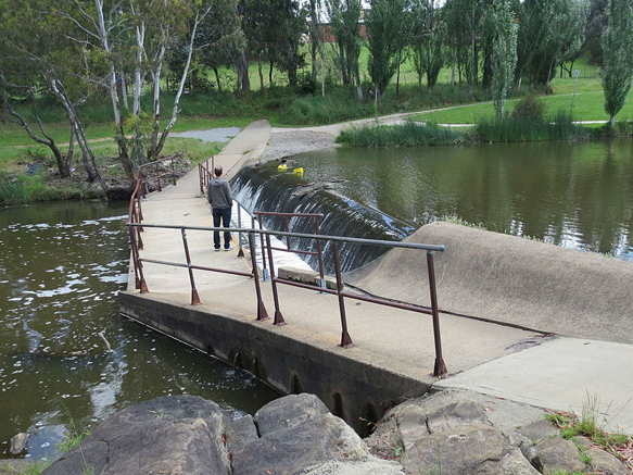
Figure 1.1: A weir on the Yass River, New South Wales, Australia directly upstream from a shared pedestrian-bicycle river crossing
1.3.4. Types of weirs:
Weirs are classified according to:
- Shape of opening
- Shape of crest
1.3.4.1. Types of Weirs based on Shape of the Opening:
- Rectangular weir
It is a standard shape of weir. The top edge of weir may be sharp crested or narrow crested. It is generally suitable for larger flowing channels.
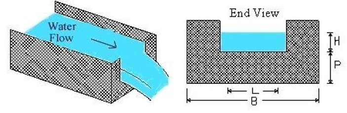
Figure 1.2: Rectangular shaped weir
- Triangular weir
The shape of the weir is actually reverse triangle like V. so, it is also called V-notch weir. This type of weirs are well suitable for measuring discharge over small flows with greater accuracy.
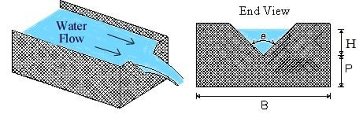
Figure 1.3: Triangular shaped weir
- Trapezoidal weir
Trapezoidal weir is also called as Cippoletti weir. This is trapezoidal in shape and is the modification of rectangular weir with slightly higher capacity for same crest strength. The sides are inclined outwards with a slope 1:4.
1.3.4.2. Types of Weirs based on Shape of the Crest:
- Sharp-crested weir
The crest of the weir is very sharp such that the water will springs clear of the crest. The weir plate is beveled at the crest edges to obtain necessary thickness. And weir plate should be made of smooth metal which is free from rust and nicks. Flow over sharp-crested weir is similar as rectangular weir.
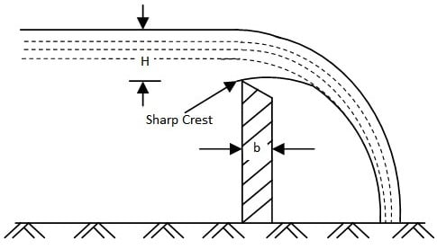
Figure 1.5: Sharp crested weir
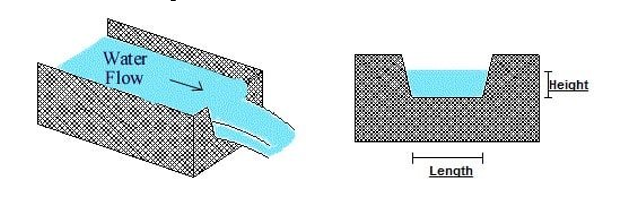
- Broad- crested weir
These are constructed only in rectangular shape and are suitable for the larger flows. Head loss will be small in case of broad crested weir. A weir having a wide crest is known as broad crested weir. If 2L>H, the weir is called broad crested weir.
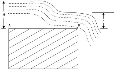
Figure 1.6: Broad crested weir
- Narrow-crested weir
It is similar to rectangular weir with narrow shaped crest at the top. The discharge over narrow crested weir is similar to discharge over rectangular weir. If 2L<H, it is called narrow crested weir.
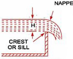
Figure 1.7: Narrow crested weir
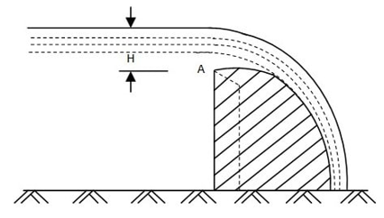
- Ogee-shaped weir
Generally, ogee shaped weirs are provided for the spillway of a storage dam. The crest of the ogee weir is slightly rises and falls into parabolic form. Flow over ogee weir is also similar to flow over rectangular weir.
1.3.4.3. Types of weirs based on Effect of the sides on the emerging nappe:
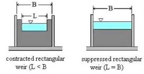
- Weir with end contraction (contracted weir)
The crest is cut in the form of notch and then it is similar to rectangular weir. Head loss will occur in this type.
- Weir without end contraction (suppressed weir)
The crest is running all the way across the channel so head loss will be negligible.
 (a) (b)
Figure 1.9: (a) Contracted rectangular weir (b) Suppressed rectangular weir
1.3.5. Ogee weir:
The ogee spillway, also known as the overflow spillway, is a control weir having an ogee (S-shaped) overflow profile. It is probably the most extensively used spillway to safely pass the flood flow out of a reservoir. The crest profile of the spillway is so chosen as to provide a high discharge coefficient without causing dangerous cavitation conditions and vibrations.
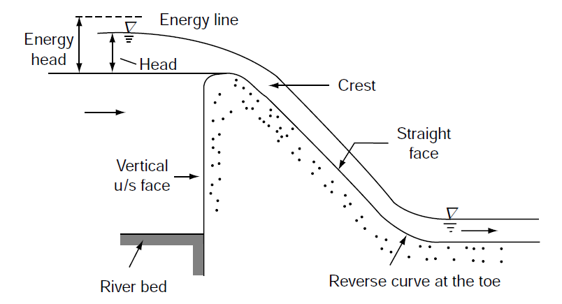
Figure 1.10: Detailed diagram of ogee spillway
Ogee weirs are usually designed in the shape of ogee curve. The crest of the ogee weir is slightly rising and falls into parabolic form.
This ogee shaped structure is used as weir, ogee spillway in dam and ogee fall in irrigation canal. This type of ogee fall was constructed by Sir Proby Causley on the Ganga canal. Whether it is a weir or spillway or canal fall, the name ogee is given for the shape of crest. The crest has gradually convex and concave surfaces. This profile of crest provides smooth transition, just to eliminate disturbance and impact. The erosion downstream by falling is minimized.
Generally, ogee shaped weirs are provided for the spillway of a storage dam.
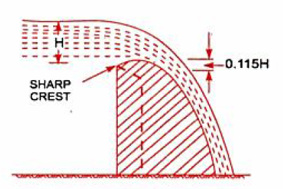
In ogee weir, crest of weir rises up to maximum height of 0.115H (where “H” is height of water above inlet of the weir) and then falls as shown in figure below.
1.3.5.1. Flow over ogee weir
The flow over an ogee weir can be computed using following equation.
Q=CLH 3/2
Where;
Q = discharge over the weir
L = effective weir length
H = free-flow total head upstream of the weir measured relative to the crest elevation
C = coefficient of discharge in free flow condition
1.3.5.2. Discharge coefficient of ogee weir:
The discharge coefficient for an ogee weir can be calculated using following equation
C = Q/LH3/2
1.4. Procedure:
- Set the slope of tilting flume equal to zero.
- Set ogee weir in the flume ensuring proper fitting by using plaster.
- Note down weir height and length “L” of weir crest.
- Allow the water to flow over weir by turning the pump on.
- From differential manometer, note down the differential head and see the value of discharge “Q” from calibrated table.
- Measure the head above crest “H” by measuring the depth of water above crest at upstream.
- Compute coefficient of discharge by C = Q/LH3/2
- Repeat the procedure by increasing the discharge.
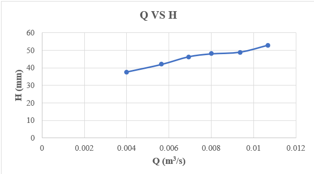
- Plot the graph between discharge and head above crest.
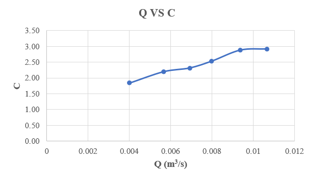
- Plot the graph between discharge and coefficient of weir.
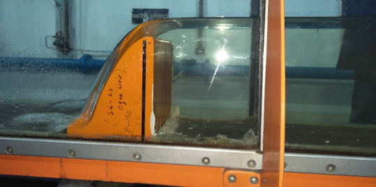
Figure 1.12: Free flow over laboratory ogee weir
1.5. observations and calculations
| Effective length of crest=L= | 300 | mm | ||||
| Crest height of weir= | 232 | mm | ||||
| Sr. no. | h1 | h2 | h1-h2 | Discharge | Head above crest | Coefficient of discharge |
| Q | H | C | ||||
| mm | mm | mm | m3/s | mm | m0.5/s | |
| 1 | 845 | 835 | 10 | 0.003999 | 37.5 | 1.84 |
| 2 | 865 | 845 | 20 | 0.005655 | 41.9 | 2.20 |
| 3 | 885 | 855 | 30 | 0.006926 | 46.3 | 2.32 |
| 4 | 880 | 840 | 40 | 0.007998 | 48 | 2.54 |
| 5 | 890 | 835 | 55 | 0.009378 | 49 | 2.88 |
| 6 | 900 | 830 | 70 | 0.01068 | 53 | 2.92 |
1.6. Results:
Average coefficient of discharge for laboratory ogee weir for free flow is 2.45.
1.7. Comments:
- As discharge increases, head above crest of ogee spillway increases.
- As discharge increases, coefficient of discharge also increases.