
4. Determination of coefficient of discharge of siphoning spillway
4.1. Objectives
- To find coefficient of discharge for siphoning spillway
- To observe pressure heads by piezometers at various point of siphon spillway
4.2. Apparatus
- S6 tilting flume arrangement
- Siphoning spillway
- Point gauge
- Piezometers
4.3. Related theory
4.3.1. Syphon spillway
A siphon spillway essentially consists of a siphon pipe, one end of which is kept on the upstream side and is in contact with the reservoir, while the other end discharges water on the downstream side. Two typical installations of siphon pipes are made which are explained below.
4.3.1.1. Tilted outlet type of a siphon spillway
The siphon pipe in figure 4.1 has been installed within the body of the dam. When the valley is very narrow and no space is available for constructing a separate spillway, the siphon pipes can be installed within dam body. An air vent may be connected with the siphon pipe. The level of the air vent may be kept at normal pool level while the entry point of the siphon pipe may be kept still lower so as to prevent the entry of debris etc. in the siphon. The outlet of the siphon may be submerged so as to prevent the entry of the air in the siphon from its downstream end.
When the water in the reservoir is upto or below the normal pool level, air enters the siphon through the vent and siphonic action cannot take place. When once the water level in the reservoir goes above the normal pool level, and if once the siphon is filled with water (i.e. it is primed); the water will start flowing through the siphon by siphonic action. The outflow will continue till the water level in the reservoir falls back to normal pool level. As soon as it happens, the air will enter the siphon through the new exposed air vent and the flow will stop.
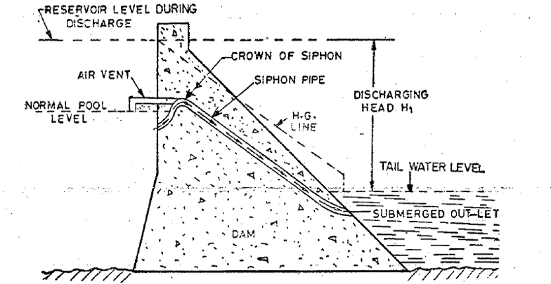
Figure 4.1: siphon pipe installed within the gravity dam
4.3.1.2. Hooded type of a siphon spillway
The construction of a hooded type of siphon spillway is more commonly adopted. In this case, a reinforced concrete hood is constructed over an ordinary overflow section of a gravity dam. The inlet of this hood is kept submerged so as to prevent the entry of debris, ice, etc. A small depriming hood is kept above the main hood and both these hoods are connected by an air vent. The inlet of the deprimer hood is kept at normal pool level. The principle of functioning of both types of installations is essentially the same, except for the initial filling up of the siphon or priming. At normal pool level (i.e. full reservoir level), the water stands up to the crest of the spillway. If now a flood enters the reservoir, the water level would start rising and a sheet of water would start flowing over the spillway crest. Since the water level is above the deprimer hood, the air entry at the inlet is sealed. The air entry at the outlet is also sealed by tail water, etc. Hence, the water spilling over the crest, sucks all the remaining air from the hood within minutes. Si phonic action gets established after the air in the bend over the crest have been completely exhausted.
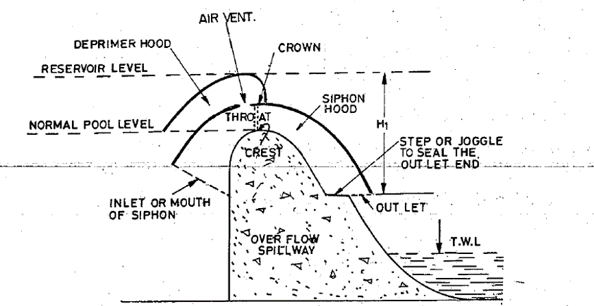
Figure 4.2: siphon installed over the overflow spillway to increase its effectiveness and discharging capacity
4.3.1.3. Laboratory siphon spillway
The laboratory siphon spillway is shown below schematically.
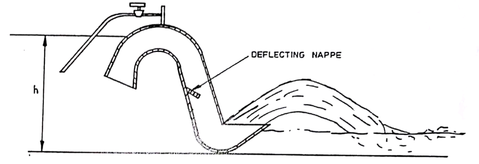
Figure 4.3: Laboratory siphoning spillway
4.4. Procedure
- Level the flume and place the siphon in the flume towards the inlet tank end.
- Open the inlet valve and gradually increase the flow to the siphon, taking great care not to overload siphon.
- It takes a little time for the siphon to prime and increasing the flow too quickly will cause the inlet channel to over top.
- Slowly allow the upstream and downstream channels to fill so that both siphon inlet and outlet are submerged.
- Downstream submergence can be produced by a weir or flume placed in the channel, or by the downstream tail gate.
- Observe and note the priming and de-priming process.
- Change the level of the breather tube and observe the effect this has on the upstream water level during priming and de-priming cycles.
- At different settings of the breather tube, operate the siphon so that it continues to run fully primed. Measure the discharge at different upstream water levels whilst maintaining a constant downstream water level using tail gate.
- Operate the siphon so that it is fully primed. Gradually raise the tailwater level and measure the effect of this on the upstream water level.
- Using the pressure tapings, measure the pressure profile along the siphon barrel when it is flowing full.
4.5. Observations and calculations
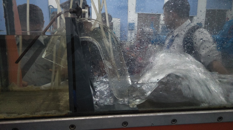
Figure 4.4: Siphoning spillway in laboratory
Area of throat = At = 0.0204 m2
| Sr. no. | ΔH | Discharge
Qact |
U/S water level | D/S water level | Head difference
h=U/S-D/S W.L |
Coefficient of discharge |
| mm | m3/s | mm | mm | mm | ||
| 1 | 4 | 0.002529 | 227 | 35 | 192 | 0.28 |
| 2 | 7 | 0.003346 | 238 | 40 | 198 | 0.37 |
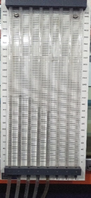
Figure 4.5: Piezometers attached at different sections of siphoning spillway
| Sr. No. | ΔH | Q | P1 | P2 | P3 | P4 | P5 |
| mm | m3/s | mm | mm | mm | mm | mm | |
| 1 | 4 | 0.002529 | 205 | 208 | 200 | 170 | 156 |
| 2 | 7 | 0.003346 | 208 | 209 | 202 | 174 | 158 |
4.6. Comments
- With increase in discharge, coefficient of discharge is increasing.
- When the breather tube is submerged in water and air vent valve is fully closed, the siphon action will be developed.
- If the breather valve is in air, the air will enter the siphon and there will be no siphoning action.